Multi Stream Power Levels with WiFi Signals
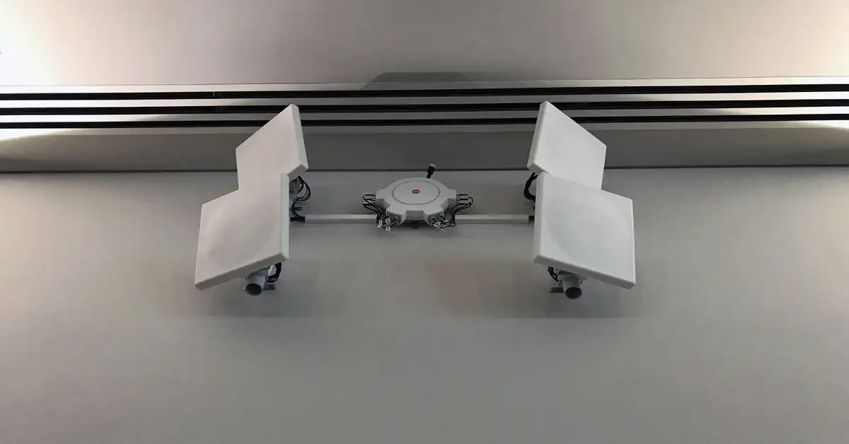
I recently started an engineering effort to validate a WiFi design and I was concerned about the signal level setting on an AP that uses directional antennas, to ensure our compliance with the local regulatory body (ACMA) requirements for spectrum management. I was particularly interested in the new four stream radios and four element antennas that are used on some of the modern WiFi implementations.
 You will note that I use a nomenclature “4×4”. The first character defines the number of streams (an independent data stream) and the second defines the number of antennas. It concerned me that I could set the power level on a radio to 20dBm whilst using a 4 stream transmission which could exceed the maximum power density limits allowed by ACMA.
For modern WiFi systems we are mainly interested at looking within the 5GHz spectrum but the following analysis would be required for 2.4GHz also. The maximum power levels allowed within the 5GHz spectrum, varies with the channels selected and is specified as an EIRP level. EIRP is a measure of the radiated power of a signal from an antenna compared to an ideal isotropic antenna. In short, it expresses a level of power as a ratio to a reference. It takes into account the electrical power output from the radio amplifiers and the gain of an antenna.
The ACMA maximum power density (within the 5GHz spectrum) is depicted in the table below:
[ut_pricing id=”4052″]
Let’s Review Power Levels
While installing a system a while ago I thought, if I have four streams with four antennas, how do I set the power levels correctly? We quite often use special antennas and the WiFi access points can’t interrogate the antenna to automatically set the power, or we use a different one to what’s programmed in the vendors equipment.
There are some guidelines from regulators like ACMA (Australia) and FCC(US) on this. I found this paper from the FCC a good read: Emissions Testing of Transmitters with Multiple Outputs in the Same Band – October 31, 2013 – 662911 D01 Multiple Transmitter Output v02r01.
This can be a complex field but the FCC states that if all the antenna elements are transmitting the same way then we simply need to add the signals together. For example, if I operate a 4×4 WiFi AP on channel 56 at a transmit level of 20dBm and the antenna gain is 2.3dB this is how I calculate the overall power level. Assume no cable losses.
- Power level at each of the antenna leads 20dBm or 100mW
- Radiated power per element 22.3dB or 167mW
- Four radiating elements adding together gives us 680mW or 28.3dBm
- Not compliant
What Signal Level Do I Need to Use?
Let’s work backwards.
- With a maximum level allowed being 200mW that means I can operate 50mW per stream.
- 50mW is 17dBm.
- Taking the gain of my antenna into consideration it means the maximum setting for power must be 14.7dB.
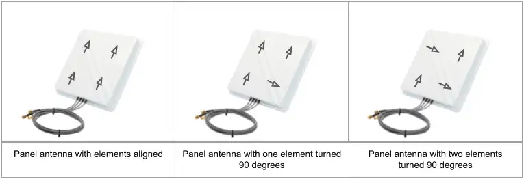
But what if I turn one of the antenna elements (1 of the 4) 90 degrees? The FCC say that the signal from this element is not adding to any of the others and they treat it as another separate signal stream. So I now only need to worry about the other 3 elements as they will deliver the most power when combined. So if I choose an antenna made this way, how do I set my power level?

We still need to work with 200mW but I can now use 66.66mW per stream or 18.23dBm. This means I can set my power level to 16dBm while using 4×4.
What if we move 2 elements 90 degrees? I could set the power to 17.7dBm.
The rough rule I use is that when all the radiating antenna elements are aligned, when I consider going from 1 element (1×1) to 2 elements (2×2) I get roughly 3dB of gain. When I go from 2 elements (2×2) to 4 elements (4×4) I get another 3dB of gain.
So if I use traditional power calculations (budgets) I need to include a 6dB gain on top of the antenna element gain when using a 4×4 transmission scheme.
For example: Transmitting on channel 157 with an antenna gain of 2.3dB (standard omni directional antenna) with a power level of 22dBm will I exceed the allowed limit?
22+2.3+6=30.3dBm or 1071mW. The limit for this channel is 4000mW so I am fine.
But how do you know how the antenna is built? Some of the more specialised manufacturers will specify the polarity of the elements and the gain for each of the elements. But who has time to work this out for every situation?
Summary
Most WiFi vendors who market volume manufactured external antennas specify a gain with the documentation but what does that mean. So I asked the manufacturers of the antennas we use to confirm if their gain in their specifications is the gain per element (of which there are 4 typically) or does this gain value include the summing effects of four spatial streams. I have found most include it. But by asking and getting a response in writing, I am covered.
In the end it was not a big thing to worry about but at least now I know!
