
Painting or Covering Antennas
Can I just paint the Antenna or the Access Point?
We very frequently need to paint or create special enclosures for antennas to minimise the impact on the aesthetics of a building. Especially in architecturally designed or Heritage listed buildings.

Some clients simply paint the antennas or the access points unaware that it will void equipment warranty and could totally disrupt the Radio Frequency (RF) propagation from the antenna. Many paints contain materials such as metals that can change the performance characteristics of an antenna (if applied to it or near it). Some plastics also can affect the performance of an antenna if placed nearby. So before we paint or cover an antenna we test the paint or material or we can test a sample antenna (before and after painting/covering). We do that using a special instrument called an RF Network Analyser.
We use a Rohde and Schwarz FSH8 in concert with a special (reference) antenna or the antenna we are planning to use. The FSH8 continuously sweeps the frequency spectrum measuring the antennas RF performance (impedance) and displays its characteristics on a Smith Chart. By sliding different materials in front of the reference antenna we can see if there are any impacts to its performance.
The exact detail of the Smith Chart is not so important for checking paint or coverings as we are looking for minimal disruption to the shape or size of the plot on the Smith Chart and maintaining the impedance. If the antennas characteristics are changed it will have a direct performance impact. For example if an Antenna has a VSWR reading of 2.0 (quite common), 10% of the power sent to it will be reflected back to the transmitter. In practical terms we would lose about 2-3dB of antenna gain.
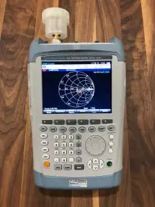 A picture of our test system is shown here. The reference antenna in this case is a 5GHz dipole (tuned to 5.48GHz) as we use this spectrum for WiFi. The paint used in the following tests was a flat black spray paint.
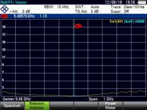
1. This chart below simply shows the VSWR of the antenna which is the ratio of transmitted to reflected signals at the antenna connector interface. Ideally it should be 1.0 (50+0j ohms) for the antenna to operate at maximum efficiency. It’s practically hard to achieve and in this case the test antenna has a VSWR of 1.1 (which is quite good).
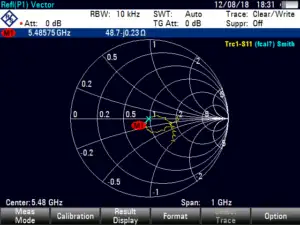
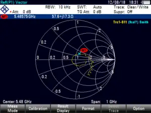
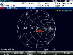
2. Below is the Smith Chart for the test antenna. It shows the vector performance (impedance) of the antenna as it sweeps a frequency range of 1GHz centred on the 5.48GHz. The goal is to have the yellow line pass through the horizontal “1” at the frequency you want to use. The marker “M1” in this case is set at 5.48GHz and it sits nicely on the “1”. The exact result is “51.5-j3.13”.

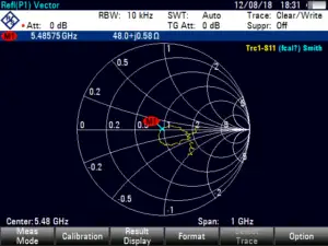
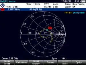
3. Below ABS Plastic white sheet (2mm) was placed directly in front of the antenna within 10mm of the dipole elements of the antenna
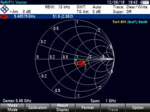
4. Below ABS Plastic white sheet (2mm) painted black was placed directly in front of the antenna within 10mm of the dipole elements of the antenna. The paint made very little difference.
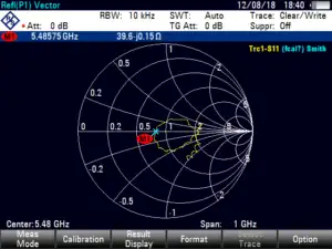
5. Below a 50mm aluminium tube was placed directly in front of the antenna within 10mm of the dipole elements of the antenna.
6. Below a brass plate was placed directly in front of the antenna within 10mm of the dipole elements of the antenna.
7. Below Wire mesh (5mm) was placed directly in front of the antenna within 10mm of the dipole elements of the antenna. Note that the impedance moved towards zero which would be a short circuit.
8. Below a PVC Flute was placed directly in front of the antenna within 10mm of the dipole elements of the antenna.
9. Below a PVC Flute with black paint was placed directly in front of the antenna within 10mm of the dipole elements of the antenna. There is no or very little difference test 9.0 and this one which indicates that this paint would be suitable to coat and antenna housing.
Ideally we are looking for no change in impedance when covering or painting an antenna so that the manufacturers specifications are maintained. To ensure this is done we take a sample reading of the first antenna before and after painting or covering. Sometimes we don’t have an option but we can at least determine how the signals will be affected and make some engineering decisions on performance expectation.
So if your wanting to make visual changes to the appearance of or structure around your AP or antenna installation, give us a call to talk through your options and find a solution that works for you.